LED灯带
如何使用外部中断
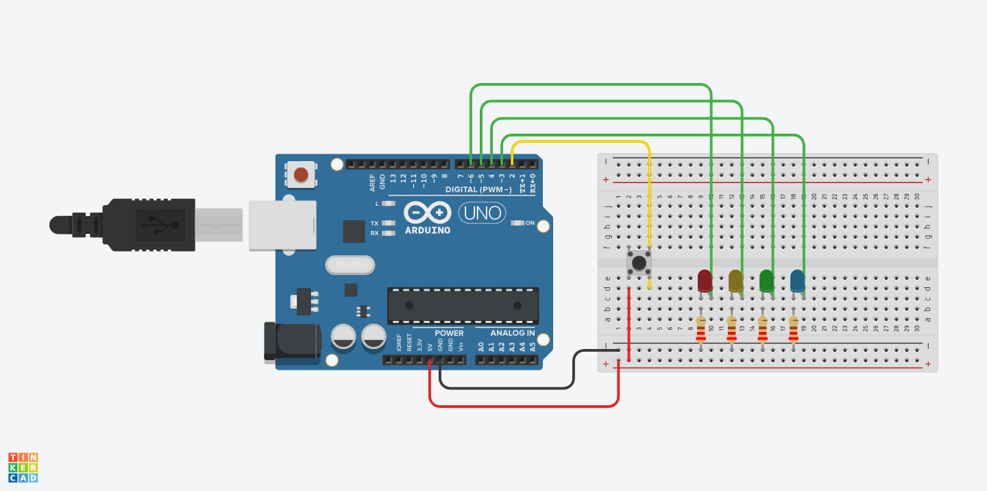
数字引脚3-6 上的 4 个 LED 依次闪烁。当 D2/INT0 上的外部中断到来时顺序颠倒。
硬件要求
- Arduino板卡
- 4个LED
- 4个220欧姆电阻
- 按钮
- 连接线
- 面包板
电路
将4个LED的正极分别接到数字引脚3-6上,负极通过220欧姆电阻接地。将一个开关一脚接到5v电源,另一角接到数字引脚2上。
板卡可中断引脚表
| BOARD | DIGITAL PINS USABLE FOR INTERRUPTS | NOTES |
|---|---|---|
| Uno Rev3, Nano, Mini, other 328-based | 2, 3 | |
| UNO R4 Minima, UNO R4 WiFi | 2, 3 | |
| Uno WiFi Rev2, Nano Every | All digital pins | |
| Mega, Mega2560, MegaADK | 2, 3, 18, 19, 20, 21 | (pins 20 & 21 are not available to use for interrupts while they are used for I2C communication; they also have external pull-ups that cannot be disabled) |
| Micro, Leonardo | 0, 1, 2, 3, 7 | |
| Zero | 0-3, 5-13, A0-A5 | Pin 4 cannot be used as an interrupt. |
| MKR Family boards | 0, 1, 4, 5, 6, 7, 8, 9, A1, A2 | |
| Nano 33 IoT | 2, 3, 9, 10, 11, 13, A1, A5, A7 | |
| Nano 33 BLE, Nano 33 BLE Sense (rev 1 & 2) | all pins | |
| Nano RP2040 Connect | 0-13, A0-A5 | |
| Nano ESP32 | all pins | |
| GIGA R1 WiFi | all pins | |
| Due | all digital pins | |
| 101 | all digital pins | (Only pins 2, 5, 7, 8, 10, 11, 12, 13 work with CHANGE) |
中断号和引脚对应表
在C/C++中,Arduino API提供了digitalPinToInterrupt(pin)函数获得引脚中断号,而无需将中断号直接放入草图中。具有中断的特定引脚及其与中断号的映射因每种类型的板而异。直接使用中断号可能看起来很简单,但当您的程序在不同的板上运行时,可能会导致兼容性问题。 然而,较旧的草图通常有直接中断号。通常使用数字 0(对于数字引脚 2)或数字 1(对于数字引脚 3)。下表显示了各种板上可用的中断引脚。 请注意,在下表中,中断编号是指传递给attachInterrupt() 的编号。由于历史原因,该编号并不总是直接对应于 ATmega 芯片上的中断编号(例如 int.0 对应于 ATmega2560 芯片上的 INT4)。
| BOARD | INT.0 | INT.1 | INT.2 | INT.3 | INT.4 | INT.5 |
|---|---|---|---|---|---|---|
| Uno, Ethernet | 2 | 3 | ||||
| Mega2560 | 2 | 3 | 21 | 20 | 19 | 18 |
| 32u4 based (e.g Leonardo, Micro) | 3 | 2 | 0 | 1 | 7 |
对于 Uno WiFi Rev2、Due、Zero、MKR 系列和 101 板,中断号 = 引脚号。
因此,引脚2对应的中断号为0,在Rust中,我们可以使用中断过程宏来触发中断处理,对应的处理函数名称为INT0
电路图

代码
该程序背后的主要思想是 LED 依次闪烁,首先降低速度,然后增加。
loop {
    blink_for_range(0..10, &mut leds);
    blink_for_range(10..0, &mut leds);
}
循环一组类似的元素(例如引脚集合),很容易将这些引脚直接放入数组中(请记住:像 Vec 这样的更高级的数据结构将需要alloc crate)。然而,每个引脚都有自己的类型,因此不能简单地将它们放入数组中。通常,引脚用于完全不同的原因,因此这个安全网是精心设计的。幸运的是 avr-hal 确实提供了一种实现阵列引脚的方法,称为降级(downgrading)
let mut leds: [Pin<mode::Output>; 4] = [
    pins.d3.into_output().downgrade(),
    pins.d4.into_output().downgrade(),
    pins.d5.into_output().downgrade(),
    pins.d6.into_output().downgrade(),
];
反转序列的一种简单方法是使用 iter_mut() 或 iter_mut().rev()。这里的问题是向前和向后迭代器具有不同的类型。幸运的是,还有另一个crate可以救援。有使用 Haskell 或 Scala 等函数式语言经验的人都会认识到,这两个crate。它提供了便利,如果 Left 和 Right 都是迭代器类型,则 Either 也将表现为迭代器类型。具体应用:
et iter = if is_reversed() {
	Left(leds.iter_mut().rev())
} else {
	Right(leds.iter_mut())
};
iter.for_each(|led| {
    led.toggle();
    arduino_hal::delay_ms(ms as u16);
})
要使任一crate正常工作,重要的是禁用 std 编译,因为这是一个no_std环境。这是通过将以下内容添加到 Cargo.toml 来实现的
[dependencies.either]
version = "1.6.1"
default-features = false
中断处理程序本身可以相当简单。约定是处理程序与其应处理的中断类型具有相同的名称,在本例中为 INT0:
#[avr_device::interrupt(atmega328p)]
fn INT0() {
    let current = REVERSED.load(Ordering::SeqCst);
    REVERSED.store(!current, Ordering::SeqCst);
}
由于中断服务例程 (ISR) 和其余代码之间存在同步问题,因此使用AtomicBool,如 Rahix 的博客文章中详细介绍的。当 ISR 执行时,不会有任何其他中断,因此不需要临界区。读取值时,需要一个关键部分,但这似乎与地址空间有关,因为 AtomicBool 应该已经提供了正确的同步:
fn is_reversed() -> bool {
    return avr_device::interrupt::free(|_| {
    	REVERSED.load(Ordering::SeqCst)
    });
}
最后要做的是将 D2 引脚切换到 EXT0 并全局打开中断:
// thanks to tsemczyszyn and Rahix: https://github.com/Rahix/avr-hal/issues/240
// Configure INT0 for falling edge. 0x03 would be rising edge.
dp.EXINT.eicra.modify(|_, w| w.isc0().bits(0x02));
// Enable the INT0 interrupt source.
dp.EXINT.eimsk.modify(|_, w| w.int0().set_bit());

unsafe { avr_device::interrupt::enable() };
让代码运行并按下按钮会显示正在运行的中断。
编译并运行示例
cargo build
cargo run
完整代码如下:
src/main.rs
/*!
 * Blinks a 4 leds in sequence on pins D3 - D6. When an external interrupt on D2/INT0 comes in
 * the sequence is reversed.
 *
 * Note: The use of the either crate requires the deactivation of std to use it in core. See the Cargo.toml
 * in this directory for details.
 */
#![no_std]
#![no_main]
#![feature(abi_avr_interrupt)]

use panic_halt as _;
use core::sync::atomic::{AtomicBool, Ordering};
use arduino_hal::port::{mode, Pin};
use either::*;

static REVERSED: AtomicBool = AtomicBool::new(false);

fn is_reversed() -> bool {
    REVERSED.load(Ordering::SeqCst)
}

#[avr_device::interrupt(atmega328p)]
fn INT0() {
    let current = REVERSED.load(Ordering::SeqCst);
    REVERSED.store(!current, Ordering::SeqCst);
}

fn blink_for_range(range: impl Iterator<Item = u16>, leds: &mut [Pin<mode::Output>]) {
    range.map(|i| i * 100).for_each(|ms| {
        let iter = if is_reversed() {
            Left(leds.iter_mut().rev())
        } else {
            Right(leds.iter_mut())
        };
        iter.for_each(|led| {
            led.toggle();
            arduino_hal::delay_ms(ms as u16);
        })
    });
}

#[arduino_hal::entry]
fn main() -> ! {
    let dp = arduino_hal::Peripherals::take().unwrap();
    let pins = arduino_hal::pins!(dp);

    // thanks to tsemczyszyn and Rahix: https://github.com/Rahix/avr-hal/issues/240
    // Configure INT0 for falling edge. 0x03 would be rising edge.
    dp.EXINT.eicra.modify(|_, w| w.isc0().bits(0x02));
    // Enable the INT0 interrupt source.
    dp.EXINT.eimsk.modify(|_, w| w.int0().set_bit());

    let mut leds: [Pin<mode::Output>; 4] = [
        pins.d3.into_output().downgrade(),
        pins.d4.into_output().downgrade(),
        pins.d5.into_output().downgrade(),
        pins.d6.into_output().downgrade(),
    ];

    unsafe { avr_device::interrupt::enable() };

    loop {
        blink_for_range(0..10, &mut leds);
        blink_for_range((0..10).rev(), &mut leds);
    }
}